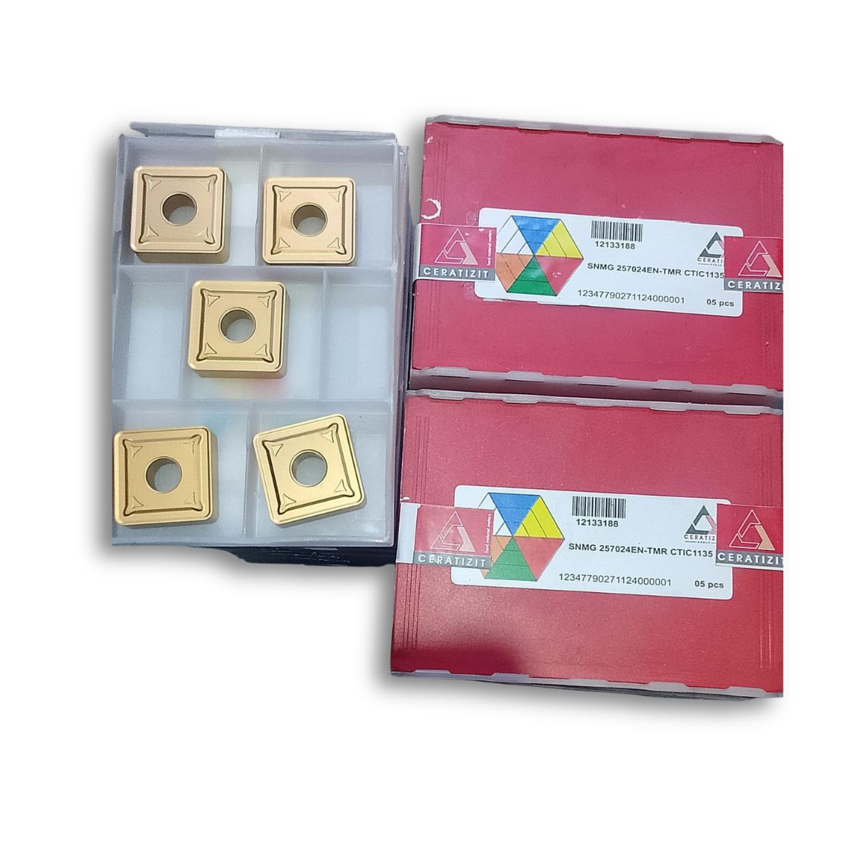
The exact breakdown of this complex ISO alphanumeric identifier dictates its physical geometry, dimensions, chip-control mechanics, and metallurgy:
1. S — Insert Geometric Profile
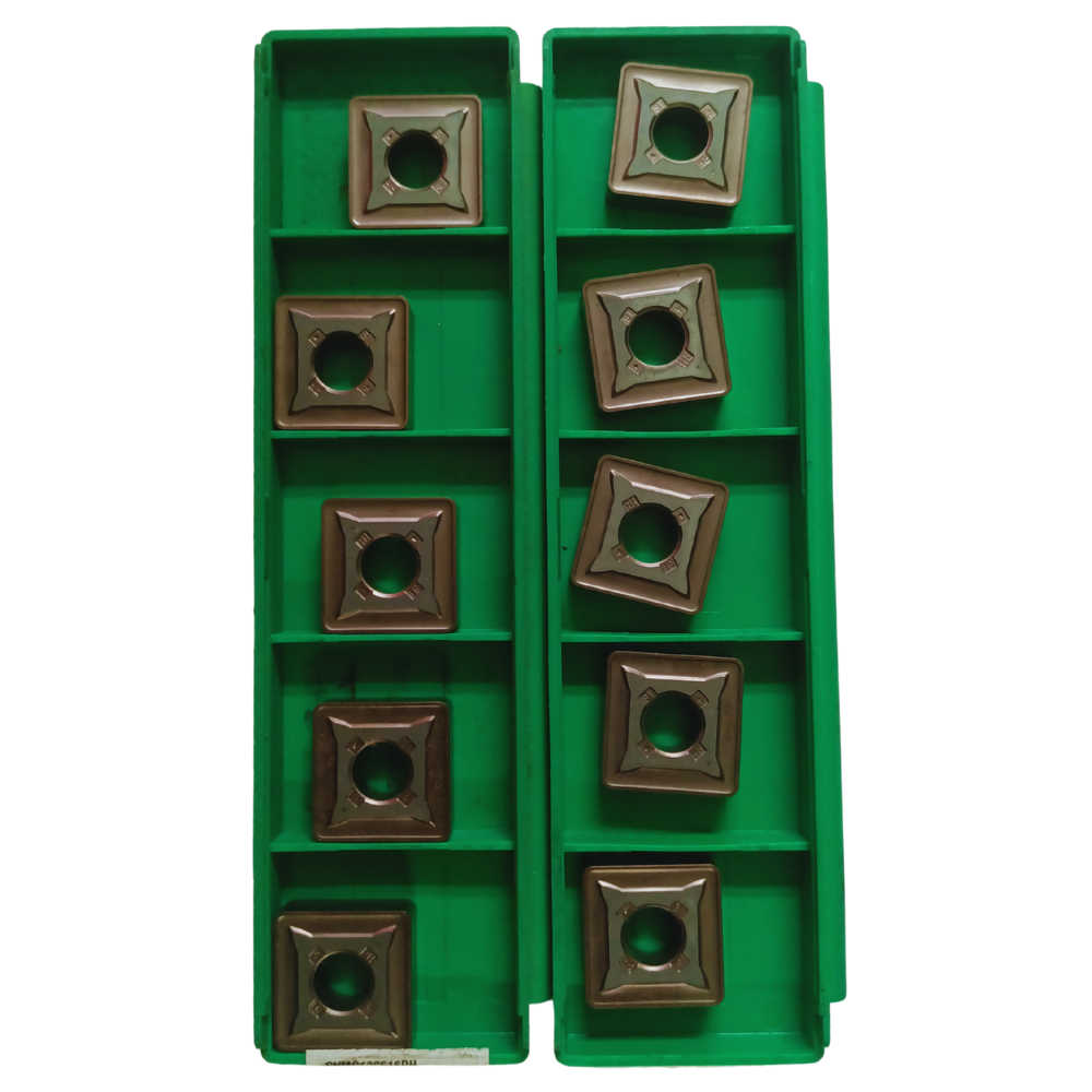
Definition: Represents a 90° Square shape.
Engineering Context: The square design provides exceptional cutting edge strength SNMG Insert for High-speed Turning and Facing Operations. Because it possesses a large 90° nose profile, it manages tremendous mechanical shock loads during roughing operations, making it highly fracture-resistant SNMG Insert for High-speed Turning and Facing Operations.
2. N — Normal Clearance Angle
Definition: Denotes a 0° (Negative) Relief Angle SNMG Insert for High-speed Turning and Facing Operations.
Engineering Context: Negative profiles allow the insert to feature cutting edges on both the top and bottom faces, effectively providing a total of 8 indexable cutting edges per insert SNMG Insert for High-speed Turning and Facing Operations. This layout requires a negatively canted tool holder pocket to generate the necessary working clearance against the workpiece.
3. M — Tolerance Class
Definition: Dictates an ISO-standard manufacturing tolerance class SNMG 190612EN-TMR CTC1135 - turning insert - ToolsUnited.
Engineering Context: Controls the precision limits of the insert's thickness, height, and inscribed circle dimensions, ensuring predictable component accuracy when flipping to a fresh cutting edge.
4. G — Clamping & Mechanical Features
Definition: Specifies a double-sided insert featuring a central cylindrical fixing hole and molded chip-breakers on both faces SNMG 190612EN-TMR CTC1135 - turning insert - ToolsUnited.
Engineering Context: The central hole enables secure high-pressure top-and-hole clamping (such as the D-style or P-style leverage lever systems) to rigidly stabilize the insert under deep plunging forces.
5. 25 — Cutting Edge Length
Definition: Represents a massive nominal cutting edge length of 25.4 mm (1 Inch).
Engineering Context: This defines an extraordinarily large insert sizing built exclusively for heavy-machining applications (heavy roughing of large structural bar stocks, forgings, or castings) where the depth of cut (
) can scale incredibly deep in a single pass.
6. 07 — Insert Thickness
Definition: Specifies a metric structural thickness of 7.94 mm.
Engineering Context: This reinforced thickness prevents structural deflection and safely absorbs intense thermal stresses or shock loads that would instantly shatter smaller standard inserts.
7. 24 — Corner Radius (Nose Radius)
Definition: Represents a heavy-duty nose radius of 2.4 mm.
Engineering Context: A 2.4 mm radius maximizes the strength of the tooltip, severely reducing the risk of edge chipping or tip fracturing during high-feed roughing passes. It also enables high feed rates (f) while maintaining safe structural limits.
8. EN-TMR — Edge Geometry & Chipbreaker Profile
Definition: The TMR represents Ceratizit's proprietary heavy-roughing chipbreaker geometry SNMG 190612EN-TMR CTC1135 - turning insert - ToolsUnited.
Engineering Context: Designed with highly stable, reinforced cutting edges featuring positive rakes to reduce power consumption while curling and snapping thick, dense chips safely out of deep cuts.
9. CTIC1135 — Metallurgical Substrate & Coating Grade
Definition: Represents Ceratizit’s premium PVD-coated Cermet or Carbide tool grade CoreLine – VNMG - Cuttingtools Ceratizit.
Engineering Context: This advanced grade balances extreme structural toughness with superior wear-resistant properties. The multi-layered coating acts as a thermal shield to prevent crater wear and thermal micro-cracking, and significantly deters built-up edge (BUE) formation when machining sticky high-temperature alloys or carbon steels