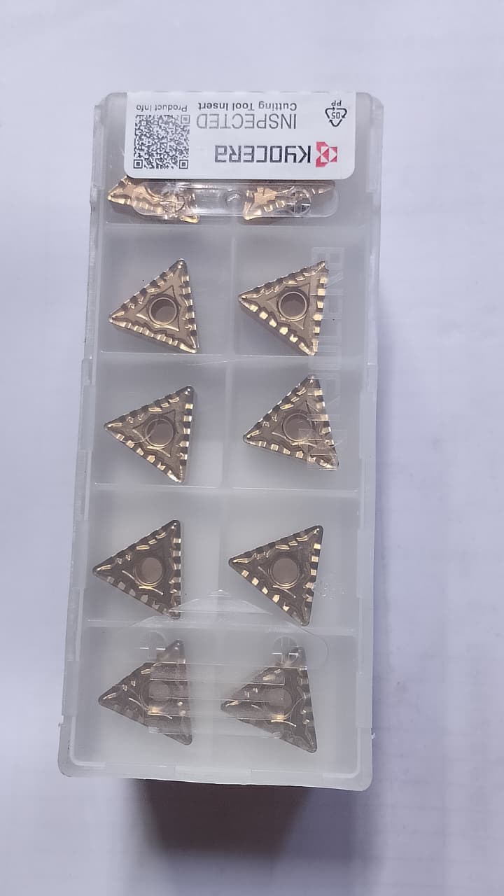
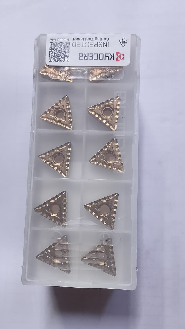
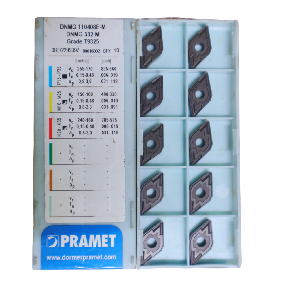
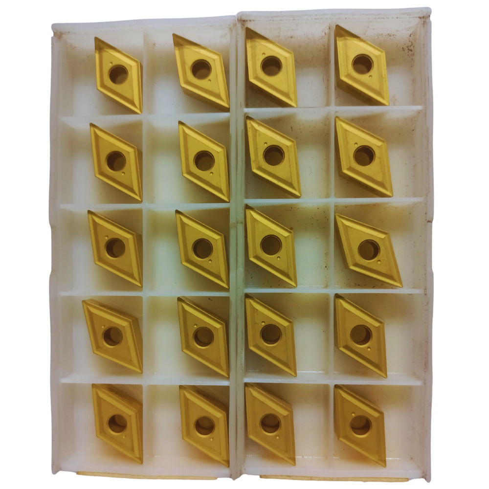
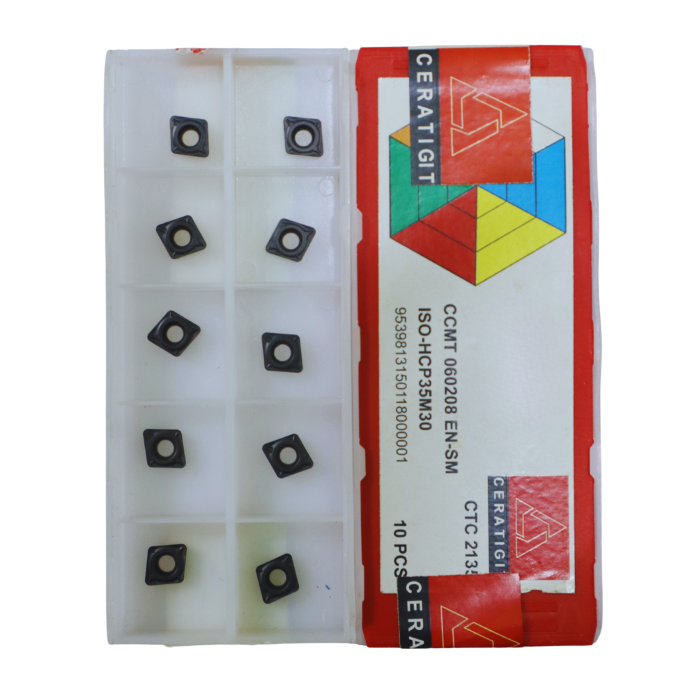
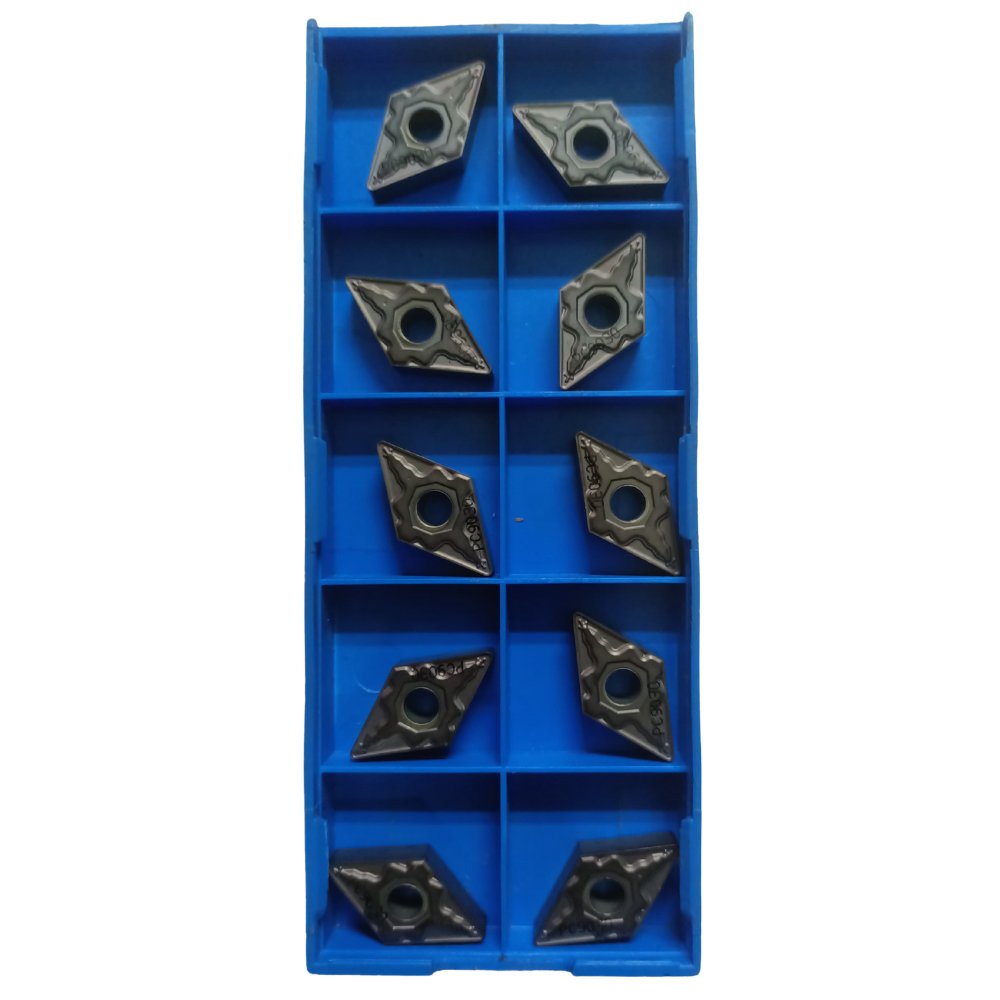
The ISO-standard alphanumeric configuration TNMG 160408CQ CV325P defines every geometry parameter, mechanical dimension, chipbreaker profile, and metallurgical layer property of the insert:
1. T — Insert Shape Profile
Definition: Represents a 60° Triangular profile.
Engineering Context: The triangular configuration provides high versatility for longitudinal turning and facing operations.
2. N — Normal Clearance Angle
Definition: Denotes a 0° (Negative) Relief Angle.
Engineering Context: Negative profiles allow the insert to feature cutting edges on both the top and bottom faces, providing a total of 6 indexable cutting edges per tip to optimize tool longevity and cost efficiencY
3. M — Tolerance Class
Definition: Specifies the precision manufacturing tolerance limits of the insert's mechanical parameters.
Engineering Context: Controls the micro-variations across the inscribed circle, thickness, and indexable heights, guaranteeing uniform workpiece dimensions when flipping to a fresh cutting edge.
4. G — Clamping & Core Structural Feature
Definition: Represents a double-sided insert equipped with a cylindrical fixing hole and molded chip-breakers on both faces.
Engineering Context: The center hole handles standard CNC rigid top-and-hole lever or wedge clamping mechanisms, ensuring the insert does not shift under heavy axial cutting forces.
5. 16 — Cutting Edge Length
Definition: Represents an ISO nominal cutting edge length of 16.5 mm (roughly a 3/8-inch Inscribed Circle size).
Engineering Context: This sizing represents the industry standard for small-to-medium general lathe turning applications, balancing cutting depth capability with structural stability.
6. 04 — Insert Thickness
Definition: Denotes a standard metric thickness of 4.76 mm.
Engineering Context: The structural cross-section is robust enough to absorb the intense mechanical impacts and vibrations encountered during continuous or light-interrupted cuts.
7. 08 — Corner Radius (Nose Radius)
Definition: Denotes a precise nose radius of 0.8 mm.
Engineering Context: The 0.8 mm configuration provides an optimal balance between tooltip strength and fine surface finish capabilities, allowing for higher feed rates without compromising the component's Ra surface finish values.
8. CQ — Chipbreaker Configuration Style
Definition: Represents Kyocera's proprietary CQ semi-finishing to medium-roughing chipbreaker.
Engineering Context: Engineered with a positive rake inclination to minimize cutting resistance and power consumption. The geometry curls long, problematic ribbons of metal into small, distinct, manageable curls, reducing machine downtime and part scratching
9. CV325P — Metallurgical Substrate & Coating Grade
Definition: Represents Kyocera’s premium CVD (Chemical Vapor Deposition) coated carbide grade.
Engineering Context: This advanced grade falls within the ISO P15–P30 application range. It incorporates a hard, wear-resistant multi-layered ceramic coating that provides high thermal insulation, effectively shielding the inner tungsten carbide substrate from micro-chipping and crater wear during continuous dry or high-speed wet machining cycles.