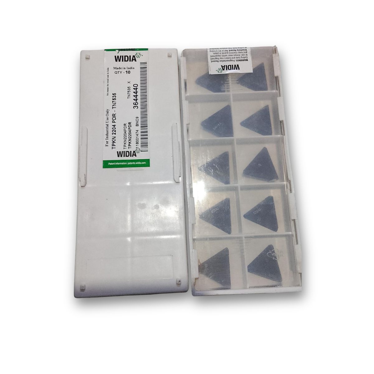
The alphanumeric ISO/ANSI code TPKN 2204 PDR-TN7535 defines every mechanical dimension, structural geometry, and metallurgical coating property of the insert:
1. T — Insert Shape
Definition: Represents a 60° Triangular profile.
Engineering Context: The triangular geometry provides three indexable cutting edges per insert. This structural shape distributes radial and axial forces uniformly during deep face milling or heavy metal slabbing operations.
Definition: Denotes an 11° Normal Clearance Angle.
Engineering Context: This positive clearance profile prevents the flank face of the insert from rubbing against the freshly machined surface of the workpiece. It is critical for maintaining lower cutting temperatures and minimizing friction during heavy material removal.
Definition: Dictates the standard industrial manufacturing tolerance class (Class K).
Engineering Context: Class K ensures highly precise indexability across the inscribed circle diameter, thickness, and absolute height parameters. This accuracy guarantees consistent surface finishes and reliable positioning when swapping edges inside multi-tip face milling heads.
4. N — Clamping / Chipbreaker Feature
Definition: Represents a single-sided insert featuring a Plain, Flat Top Profile without a formed chipbreaker groove.
Engineering Context: The smooth, ungrooved face offers maximal structural core strength. It relies on standard wedge or clamp-on milling head fixtures to secure it, making it resilient against intense impact shocks encountered during rough, interrupted cuts on scale-covered metals.
5. 22 — Cutting Edge Length
Definition: Indicates a nominal cutting edge length of 22 mm.
Engineering Context: This measures out to a standard 1/2-inch Inscribed Circle (IC) size. The large physical size provides a high depth of cut capacity (APMX), allowing the mill to remove large volumes of stock in fewer passes.
Definition: Specifies a standard metric thickness of 4.76 mm (3/16 inch).
Engineering Context: This thickness is engineered to support the extended 22 mm edge length. It effectively resists bending stresses, structural deflection, and catastrophic fracture when encountering heavy feeds per tooth
7. PDR — Edge and Feed Direction Geometry
Definition: Represents a Right-Hand cutting direction (R) with a specific corner design featuring a planar facet/wiper edge.
Engineering Context: The "PD" profile ensures optimized entry angles for face milling cutters. The "R" configuration dictates that it mounts into right-hand clockwise rotating milling holders. It provides strong edge reinforcement to prevent micro-chipping under intense structural stress.
8. TN7535 — Metallurgical Substrate & Coating Grade
Definition: Represents a specialized Premium Coated Carbide Grade engineered by Widia.
Engineering Context: Built upon a shock-resistant structural tungsten carbide substrate, the TN7535 grade features advanced multi-layer coatings (typically CVD or high-density PVD TiN/TiAlN composites). This combination forms a reliable thermal barrier that protects the inner core against immense heat generation, resists built-up edge (BUE) formation, and minimizes abrasive.