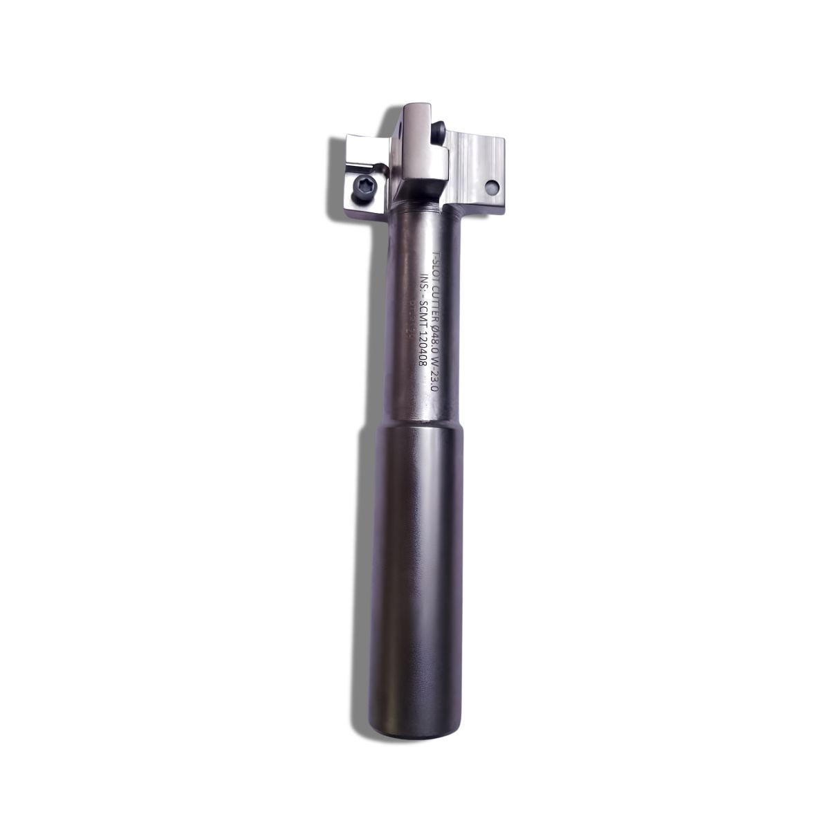
Q48.0W: This specifies the Cutting Head Diameter (\(D_{c}\)) is exactly 48.0 mm. This dictates the maximum wide bottom horizontal profile of your T-slot channel.
23.0: This indicates the Cutting Width / Insert Face Thickness (\(a_{p}\)) is exactly 23.0 mm. It tells you how tall the wide internal lower T-cavity will be on each horizontal pass.
INS: SCMT 120408: This identifies the exact indexable carbide insert style required to populate the cutter pockets.
📐 Insert Mechanics (SCMT 120408)
S: Square shape (90-degree corner profile), providing maximum edge strength and stability under high lateral loads.
C: 7° Positive clearance angle, which lowers cutting friction and reduces the spindle horsepower required to drive a 48mm head through a blind pocket.
M: Standard manufacturing tolerance class for a secure, rigid seating inside the cutter body pockets.
T: Single-sided design featuring a countersunk screw-clamping lock hole for flush mounting so chips do not snag on the hardware.
12: The nominal cutting edge length is approximately 12.7 mm (1/2 inch).
04: The thickness of the insert is exactly 4.76 mm (3/16 inch).
08: The corner nose radius is 0.8 mm, creating a strong, radius-strengthened fillet at the bottom internal corner of the T-slot to prevent stress fractures in the workpiece.
⚙️ Operational Best Practices
Pre-Slotting Step: You cannot plunge this tool straight into solid metal. A standard end mill must first clear a vertical pilot slot that is wider than this cutter's neck diameter, but narrower than 48mm.
Chip Clamping & Evacuation: Because the tool operates inside a narrow, enclosed blind horizontal channel, chips will naturally pack together. Use through-tool air blast or high-pressure coolant to forcefully flush out chips and prevent catastrophic tool breakage.
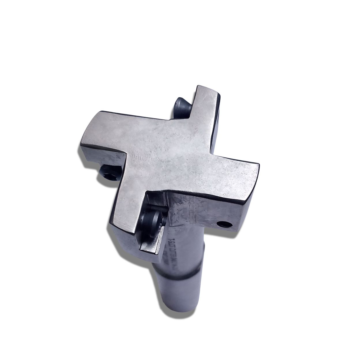
Staggered Cutting Advantage: Holders built for SCMT 1204 inserts typically alternate the inserts facing up and down along the periphery. This neutralizes heavy axial forces and prevents severe machine chatter.