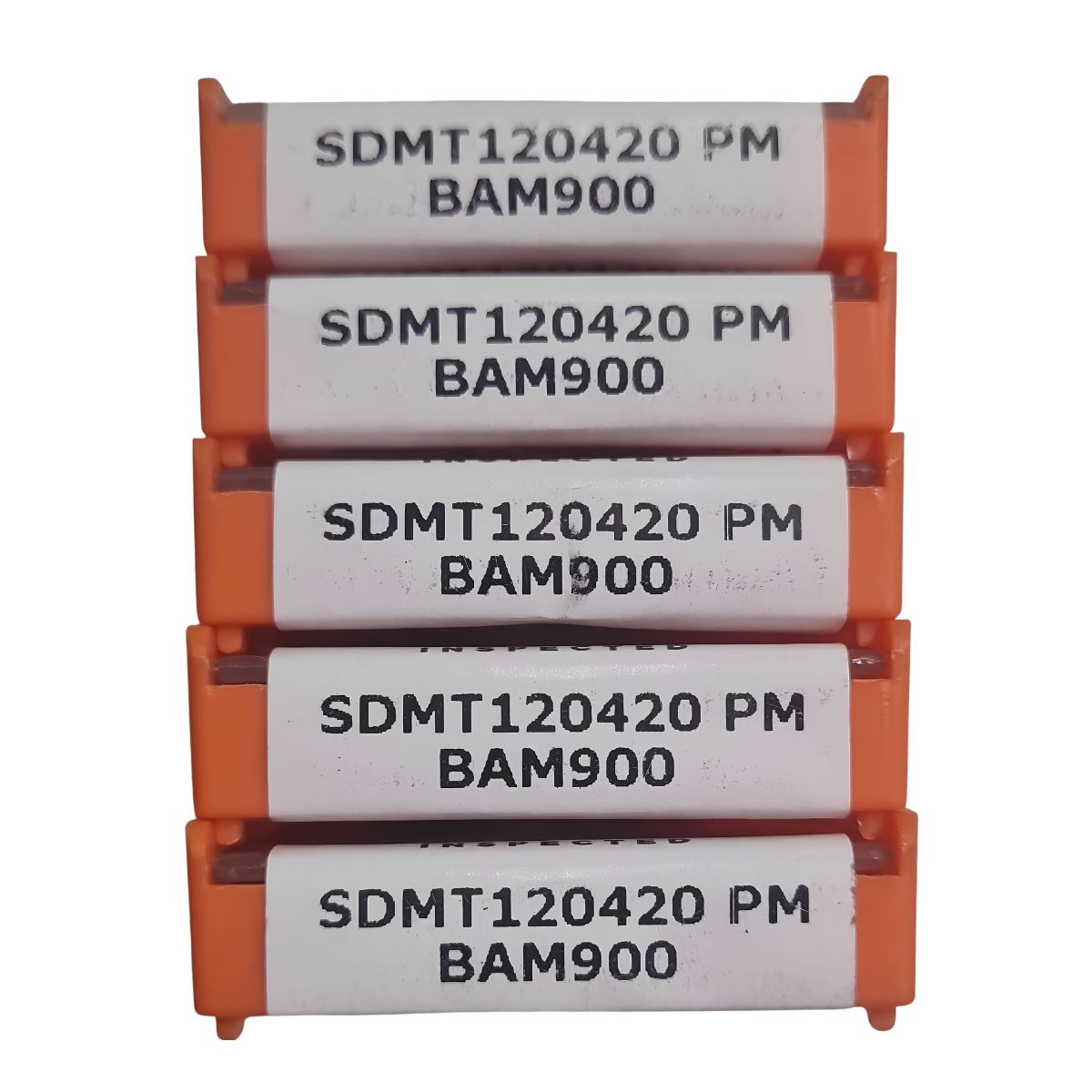
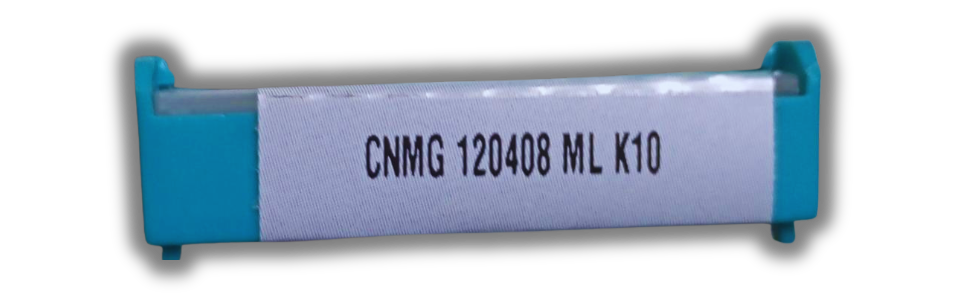
S: Square shape contour profile (provides 4 robust cutting edges per insert).
D: 15-degree normal clearance relief angle underneath the cutting face.
M: Precision tolerance level governing tool height, thickness, and IC spacing.
T: Countersunk mounting screw style with customized chip-groove configuration.
12: Inscribed Circle (IC) sizing value, denoting a cutting width parameter of 12.7 mm (approx. 0.5 inches).
04: Thickness dimension of the carbide body, measuring exactly 4.76 mm.
20: Corner radius measurement, signifying an extra-thick, durable 2.0 mm corner radius built to resist edge chipping under heavy chipping shock.
2. Application Focus (PM)
PM: Designates a Medium-Roughing Chipbreaker. This specific top face ridge is optimized for balanced chip control, preventing long, stringy chips from nesting around the face mill during standard operations across alloyed steel and cast metals.
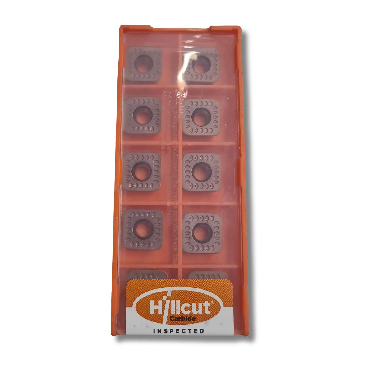
3. Core Material Grade & Coating System (BAM900)
BAM900: A specialized industrial tooling grade composed of a submicron carbide substrate matrix paired with an advanced multi-layered PVD nanocomposite coating.
Engineered specifically for high-speed milling (HSM) under challenging setups.
Optimized to combat extreme friction and high temperatures when processing carbon steels, alloy steels, and stainless steels.
Operational Cutting Range
Material Group Compatibility
Cutting Speed Range Typical Feed per Tooth
P (Carbon / Structural Steel) 140 – 260 m/min 0.15 – 0.40 mm/tooth
M (Stainless Steel Alloys) 100 – 180 m/min 0.12 – 0.30 mm/tooth
K (Grey & Ductile Cast Iron) 120 – 220 m/min 0.15 – 0.35 mm/tooth