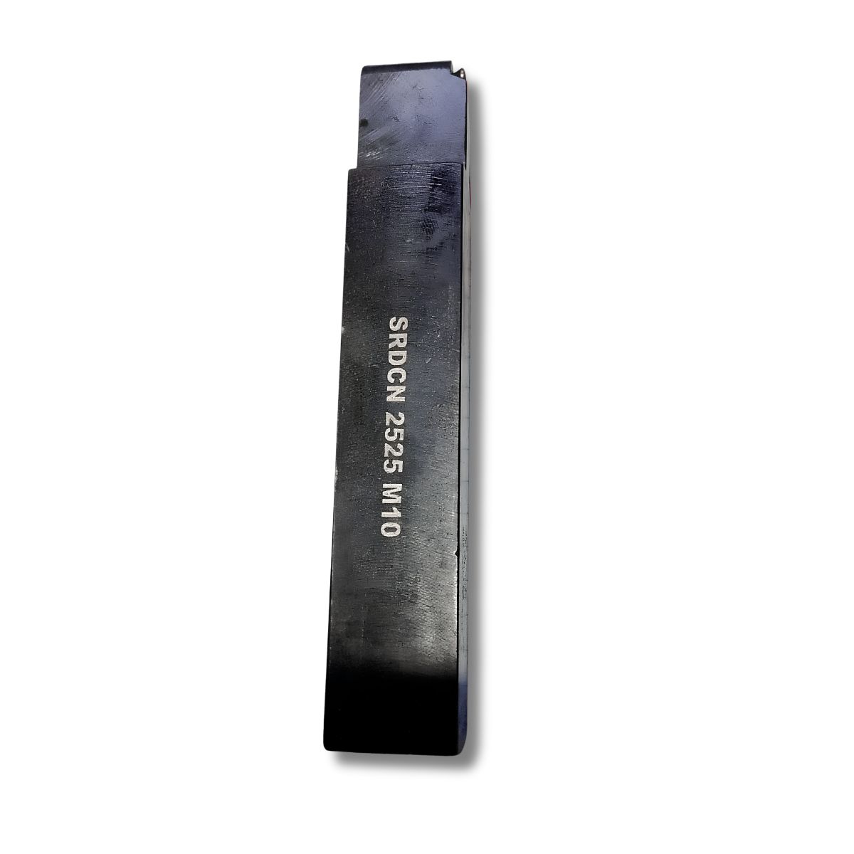
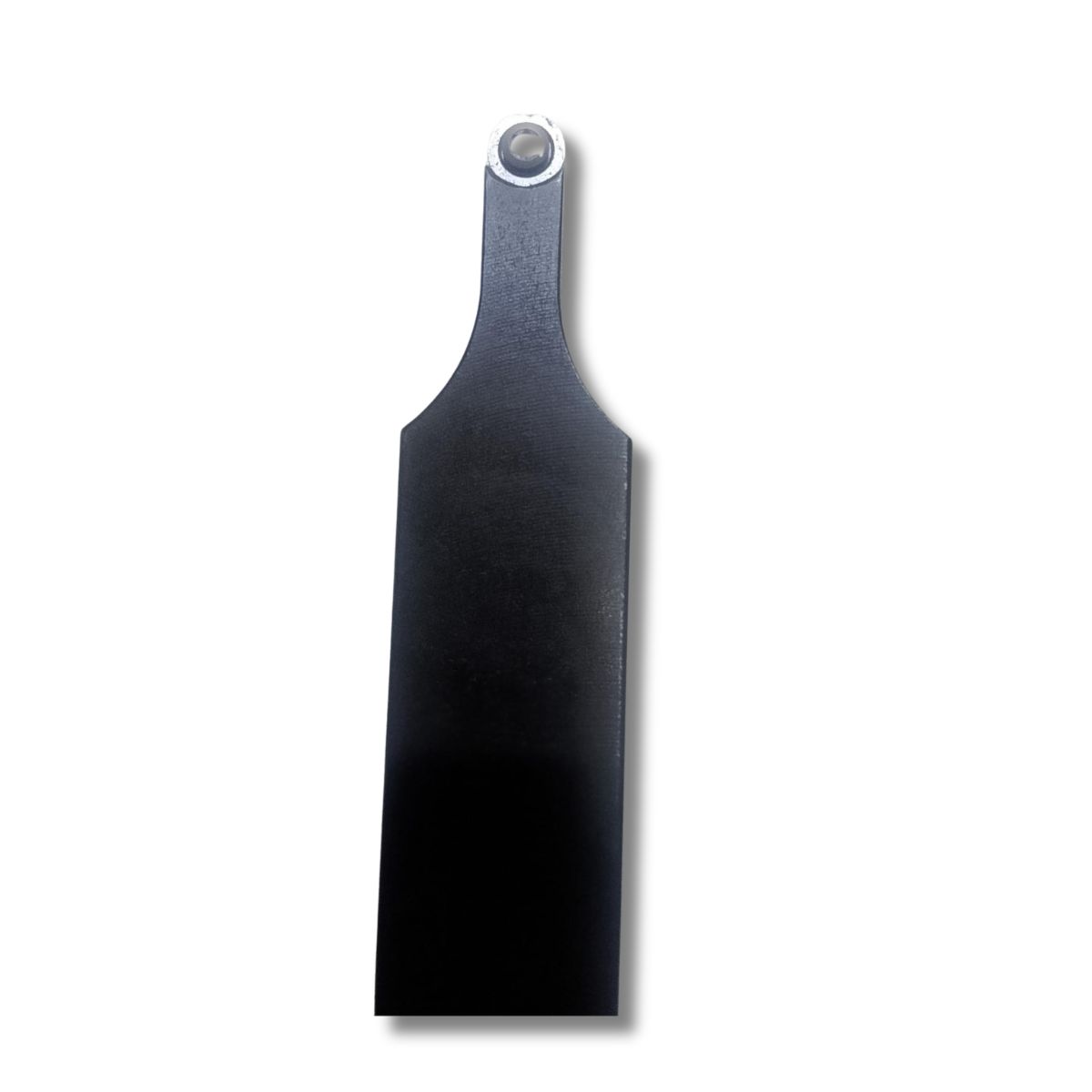
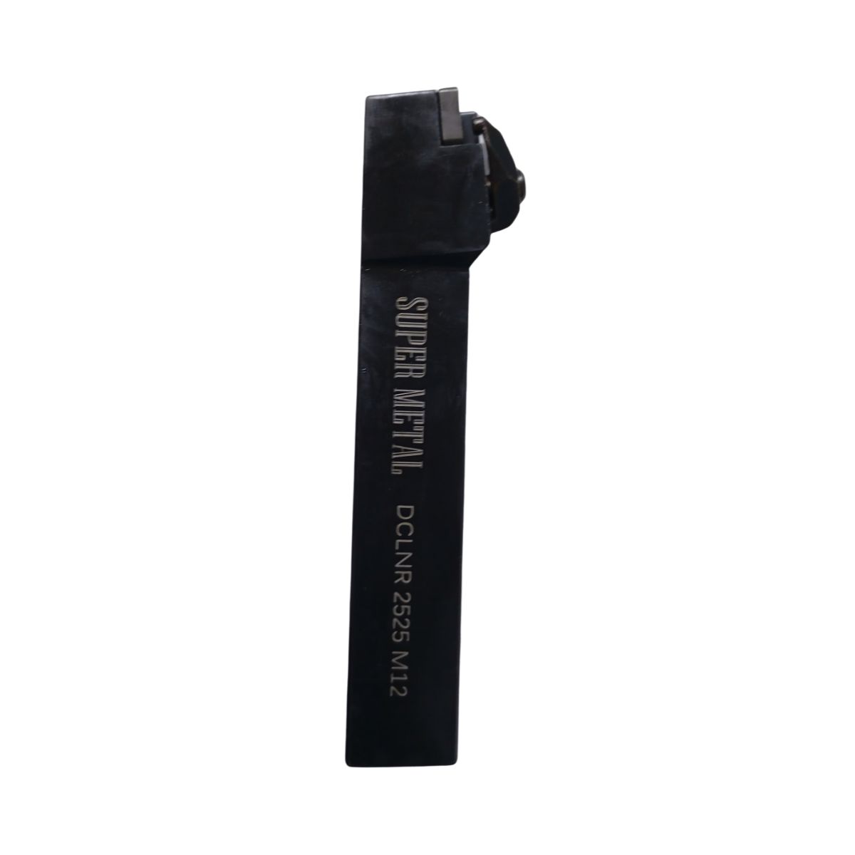
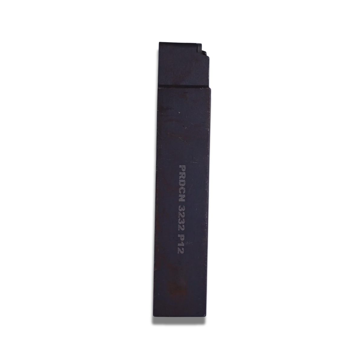
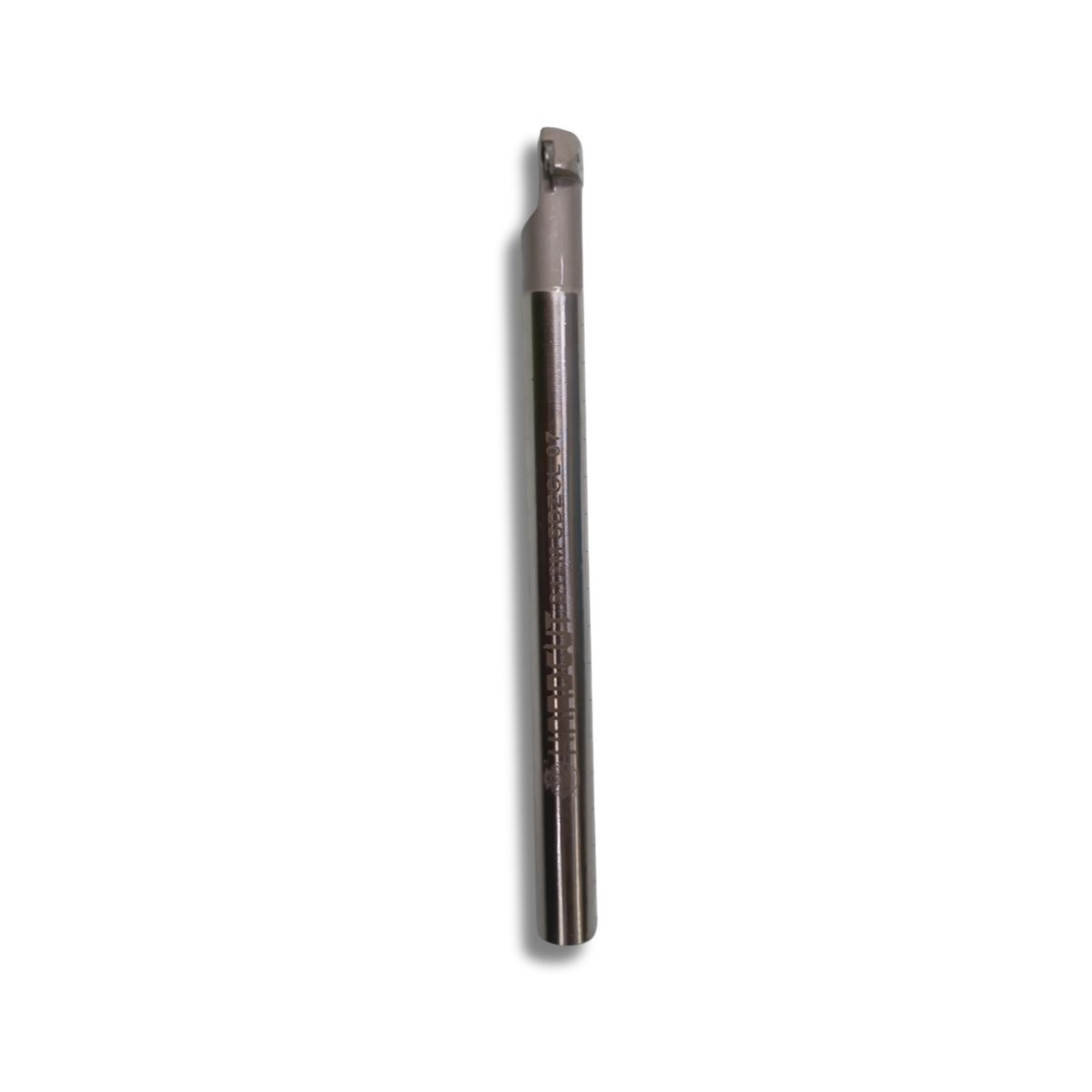
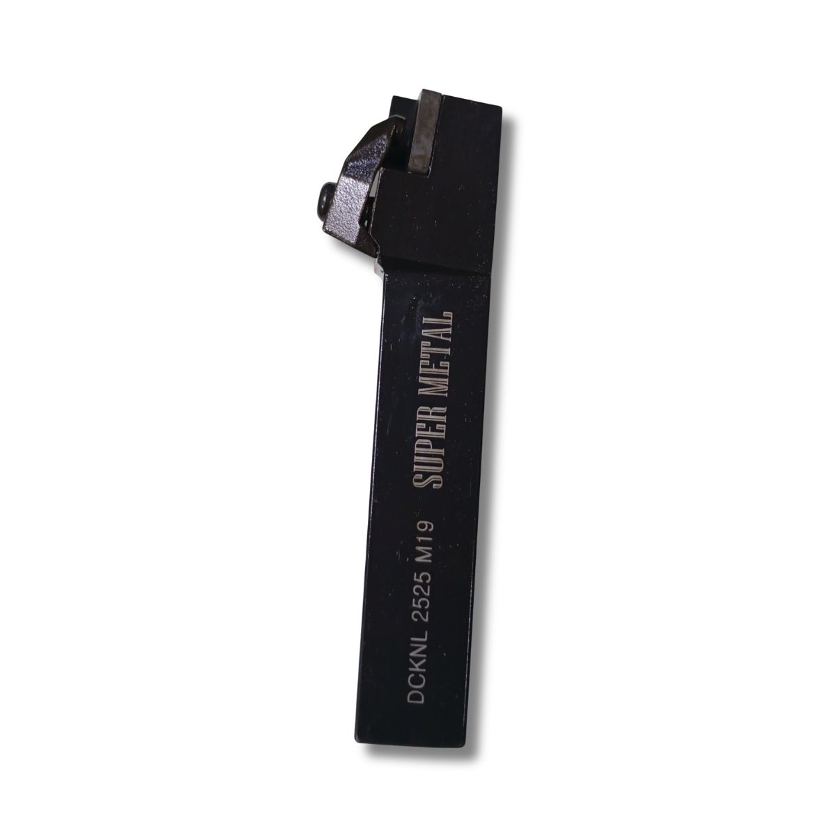
The alphanumeric ISO code SRDCN 2525 M10 provides a complete design and dimensional blueprint for the hardware body:
1. S — Clamping System
Definition: Represents a Screw-Down Clamping System utilizing a central conical screw.
Engineering Context: The insert is locked down via a single torqued screw through its center hole directly into the pocket. This compact layout leaves the top face of the tool completely clear, providing excellent chip flow and preventing nested ribbons of metal from packing inside the pocket zone.
2. R — Insert Shape
Definition: Engineered exclusively for Round (R) indexable inserts.
Engineering Context: Round geometries offer the strongest cutting edges in machining because forces are distributed across a broad radius rather than concentrated on a single sharp corner point. It allows the tool to seamlessly handle varying entry depths and heavy interrupted cuts.
3. D — Tool Holder Style (Approach Angle)
Definition: Specifies a straight shank body configuration resulting in a 45° approach angle relative to the workpiece axis.
Engineering Context: A 45° angle provides highly balanced radial and axial tool force distribution. This balance helps reduce harmonic chatter and tool deflection, which is critical when roughing down raw castings or un-machined forged skins.
4. C — Clearance Angle
Definition: Designed for round inserts featuring a 7° positive clearance angle (such as RCMT or RC.. style inserts).
Engineering Context: The pocket is precisely canted so that the 7° flank face of the round insert safely clears the workpiece surface during longitudinal passes, reducing heat friction and maximizing tool-life expectancy.
5. N — Tool Handedness (Cutting Direction)
Definition: Indicates a Neutral (N) orientation tool.
Engineering Context: Because the tool has a symmetrical center-mounted pocket layout with zero offset, it can machine and contour smoothly from both left-to-right and right-to-left directions. This flexibility eliminates the need to cycle tool changes during complex, symmetrical profiling routines. [1, 2, 3, 4]
6. 2525 — Shank Size Parameters
Definition: Denotes a robust metric square shank size of 25 mm × 25 mm.
Engineering Context: The holder features a 25 mm shank height and a 25 mm shank width. This large cross-sectional footprint offers superb rigidity and torque resistance under extreme tool pressures.
7. M — Overall Tool Length
Definition: Dictates a standard industrial tool length coded under the "M" specification, which is exactly 150 mm.
Engineering Context: This defines the total distance from the base of the shank to the tip of the tool pocket, ensuring it fits cleanly into typical lathe turret disk spaces.
8. 10 — Insert Size Accommodation
Definition: Specifies a nominal pocket capacity engineered to hold a 10 mm diameter round insert.
Engineering Context: This holder is built to tightly anchor inserts with a 10 mm inscribed circle (IC), such as the RCMT 10T3 or RPMT 10T3 series.